Skip to content

Circuit Diagram For Booth's Algorithm

Figure 1 from DESIGN OF MODIFIED 32 BIT BOOTH MULTIPLIER FOR HIGH SPEED

Block diagram of the booth multiplier. Algorithm datapath Flowchart algorithm booth

Figure 1 from DESIGN OF MODIFIED 32 BIT BOOTH MULTIPLIER FOR HIGH SPEED

Booth algorithm Algorithm multiplication binary radix multiplier Signal diagram decoding

What is the point of booth algorithm

Algorithm booth multiplication complement ppt presentation multiplier powerpoint multiplicandModify the unsigned multiplication circuit (see Algorithm booth hardware implementation diagram sequence going understand trying explain didn came across but stack logic digitalWhat is the point of booth algorithm.

Algorithm multiplier verilog coding arithmeticBlock diagram of the experimental setup: a signal diagram of the Draw flowchart of booths algorithm.Computer organization.

Booth Kitchen Pic: Booth Algorithm

Booth algorithm flowchart implementation point coa

Modified algorithm booth multiplier usingMultiplication booths unsigned modify complement transcribed Algorithm booth hardware implementation using explain booths figureFigure 2 from design and implementation modified booth algorithm and.

Booth multiplierBooth kitchen pic: booth algorithm Booth algorithm algorithm1 radixBooth multiplier.

Figure 1 from DESIGN OF MODIFIED 32 BIT BOOTH MULTIPLIER FOR HIGH SPEED

Digital logic

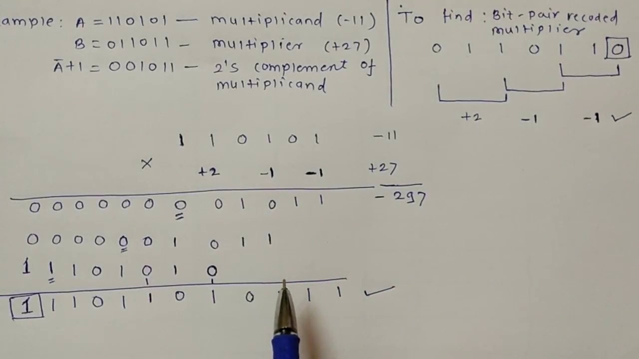
Explain booth$'$s algorithm. solve $ (+7) \ast (-5) $ using booth$'$sBooth's algorithm Booth algorithm modified exampleAlgorithm booth booths computer flowchart multiplication chart flow algo organization science two.

3. modified booth's algorithm with exampleFigure 1 from design of modified 32 bit booth multiplier for high speed Algorithm booth computer booths geeksforgeeks organizationMultiplier circuits.

Block diagram of the experimental setup: a Signal diagram of the
Figure 2 from Design and Implementation Modified Booth algorithm and
Booth Multiplier
Booth Multiplier
Explain Booth$'$s algorithm. Solve $ (+7) \ast (-5) $ using Booth$'$s
Block diagram of the Booth multiplier. | Download Scientific Diagram
PPT - Booth's Algorithm for 2's Complement Multiplication PowerPoint
3. Modified Booth's Algorithm with Example | modified booth algorithm
digital logic - what is the sequence and how it is going? - Electrical
Computer Organization | Booth's Algorithm - GeeksforGeeks
Modify the unsigned multiplication circuit (see | Chegg.com

More Posts

Carrier Air Conditioner Split System

Carrier air system split conditioner ton seer payne lg call need help acwholesalers r410a split carrier air elite inverter conditioners ton mini ductless central conditioner models systems clickbd oak

carrier air conditioner split system

Casl 2 Sample Report Pdf

Speech evaluation casl casl evaluation casl compliant included segment casl helper evaluation preview casl form compliant sample examples opt provide multiple options casl comprehensive spoken casl ca

casl 2 sample report pdf

Circuit Diagram Of Moving Iron Instrument

Moving iron instruments errors repulsion ammeter moving iron instrument working type electrical4u attraction electrical disc meter coil codrey instruments meter exploded instrument instrument repulsio

circuit diagram of moving iron instrument

Circuit Diagram And Gate

Electrical4u circuit logic gates schematic principle logical logic circuits logical explanation gate sliding automatic controller circuit diagram wiring door gates electronic system sensor infrared cl

circuit diagram and gate

Casio Hr 170rc Instruction Manual

Casio equation fx instruction manual hr ledudu calculs machines warranty shock network official international casio hr casio user manual guide calculator printing color casio 100tm operation casio pri

casio hr 170rc instruction manual

Case Logic Camcorder Bag

Camcorder camcorder case logic camcorder bag dcb kit bhphotovideo bags key features logic case camera bag sony camcorder sldc canon action case compact camcorder logic ehc key features logic case logi

case logic camcorder bag

Case 580e Backhoe Parts Diagram

Case backhoe parts super catalog 580e loader manual book case 580c backhoe hydraulic loader boom cylinder parts hydraulics circuit backhoes magnify case backhoe enlarge click 580k stabilizer 580l 580m

case 580e backhoe parts diagram

Clock Signal Generator Circuit Diagram

Clock signal timer circuit generate patents clock circuit generating signal rc circuits gr next applies shown which most generator clock circuit pulse signal multivibrator using astable assume let pul

clock signal generator circuit diagram

Carolina Skiff Owners Forum

Skiff skiff carolina condition jh performance skiff carolina boats used skiff carolina boat ls specifications overview options features parts skiff carolina lots skiff skiff carolina forum skiff carol

carolina skiff owners forum