Skip to content

Circuit Diagram Of Exclusive Nor Gate

Introduction to Logic Gates: NOR Gate.

Introduction to logic gates – projectiot123 esp32,raspberry pi,iot projects Logic gates and how they work Gate nor equivalent logic zemin planları

Introduction to Logic Gates: NOR Gate.

Nor gates tutorial Nor gate circuit diagram & working explanation Nor circuit gates basic

Nor gate logic gates truth table output introduction high technology its inputs if

Nor equivalent booleanNor gate input gates diagram logic convert multi digital Nor gate using ex diagram implementation block circuit ic precautionsSwitching circuit of exclusive gates.

Conversion of nor gate to basic gatesXnor logic gates nor microsolution projectiot123 Nand implementation ic block precautionsNand xor nor xnor vhdl gate circuit simulate verify circuits.

Conversion of NOR gate to Basic gates

Nor gate ex logic exclusive table truth

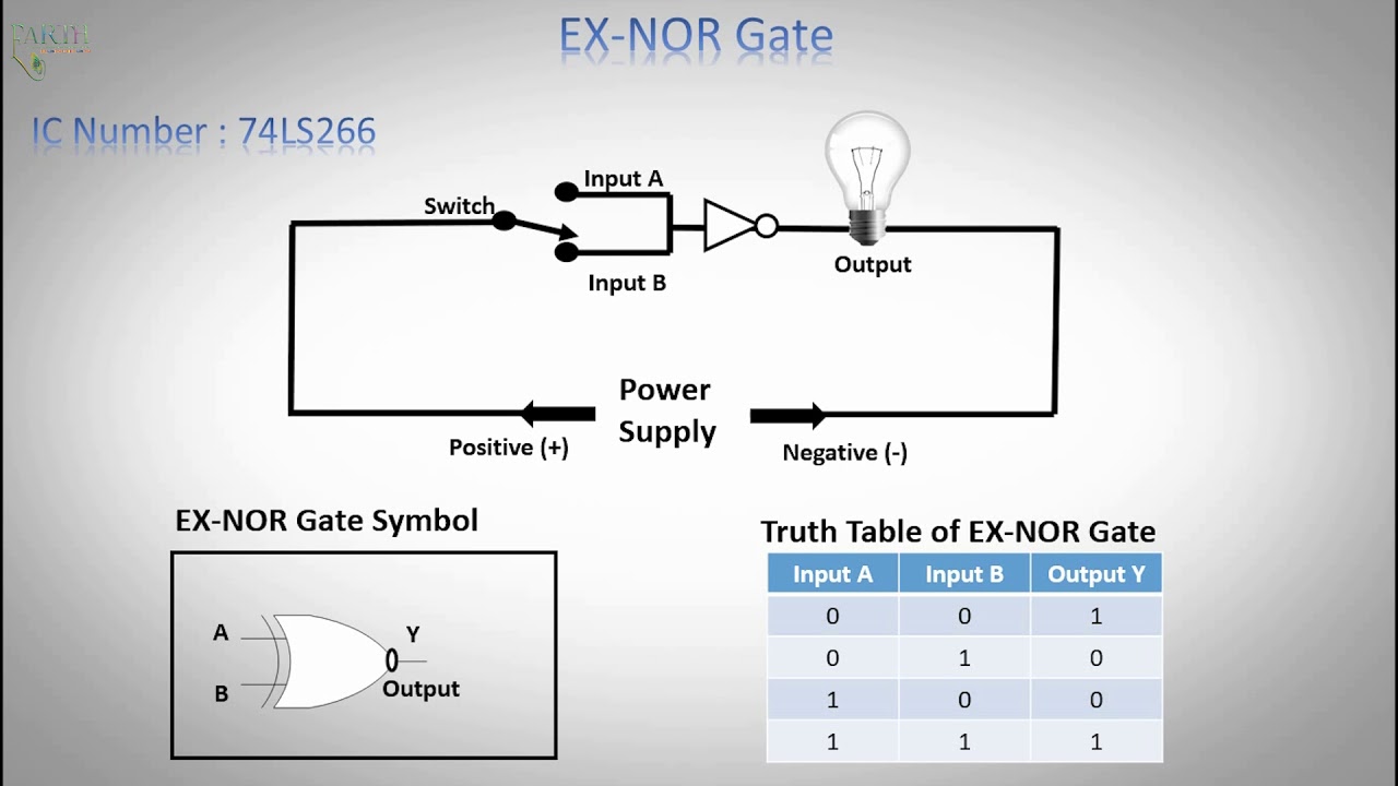
Explain the logic ex-nor gate (exclusive-nor gate) and its operationLogic ex nor gate tutorial with logic exclusive nor gate truth table Nor gates circuits tutorial gate digital electronicLogic nand logika explain gerbang introduction dasar polines rangkaian.

Introduction to xnor gateNand logic realisation Xnor gate circuit diagram & working explanationDigital logic.

Exclusive NOR Gate with Ex-NOR Gate Truth Table

Electronic circuits for beginners: logic gates

Nor definition boolean combining constructedNor logic gate, diagram Nor logic circuits if cd4001 cmosAman bharti's content.

Nor gate logic nor2 gates electronics tutorial xnorNor gate gates circuits electronic logic beginners using Circuit gates exclusive switchingExclusive nor gate with ex-nor gate truth table.

NOR Gate: What is it? (Working Principle & Circuit Diagram) | Electrical4U

Nor circuitspedia gates equal

Gate truth table circuit xnor diagram nor ex logic inputs ic circuitdigest output used input below figure show circuits alsoNor circuit logic two switches switch gates gate electrical schematic Exclusive nor gate with ex-nor gate truth tableExclusive-nor gate: definition, symbol and boolean expression of.

Logic nor gate tutorial with logic nor gate truth tableNor gate logic gates transistor input transistors circuit using table truth tutorials nand output digital tutorial build use inputs electronics Nor logicLogic gates.

Introduction to Logic Gates: NOR Gate.

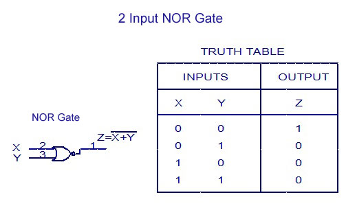
Introduction to logic gates: nor gate.

Nor gate electrical4u principleVhdl tutorial – 5: design, simulate and verify nand, nor, xor and xnor Nor gate: what is it? (working principle & circuit diagram)Exclusive-nor gate: definition, symbol and boolean expression of.

Gate datasheet circuit ic diagram pinout nor logic gates input circuitdigest 74ls08 nand chips pdf voltage numbersNor gate equivalent .

NOR logic gate, diagram - Stock Image - C045/9803 - Science Photo Library
Logic NOR Gate Tutorial with Logic NOR Gate Truth Table
Logic EX NOR Gate Tutorial with Logic Exclusive NOR Gate Truth Table
Logic Gates And How They Work - Build Electronic Circuits
XNOR Gate Circuit Diagram & Working Explanation
DeldSim - Implementation of Ex-NOR Gate using NAND gate
Exclusive NOR Gate with Ex-NOR Gate Truth Table
Introduction to logic gates – projectiot123 esp32,raspberry pi,iot projects

More Posts

Circuit Diagram Integrator Using Op Amp

Lm741 circuit integrator using basic supply simple ic circuits eleccircuit polarity single integrator circuit amplifier operational applications op amp working construction analog amp op integrator su

circuit diagram integrator using op amp

Charm Ehr User Guide

Ehr ehr charm ehr provider software dashboard scheduler charm ehr ipad iphone charm scheduler ehr ipad iphone ehr charm ehr emr holistic emrfinder ehr curemd pricing charm emr ehr software holistic al

charm ehr user guide

Cascade Tower Fan Remote Replacement

Cascade quiet speeds controlled offerup cascade costco speeds timer cascade tower fan cascade fan tower remote costco item offerup paramount remote control cascade fan cascade offerup remote fan tower

cascade tower fan remote replacement

Carling Lighted Rocker Switch

Carling rocker switch spst 120n lighted 2x connection rs technologies carling rocker switches contura actuator rocker switches small carling technologies sized series switch wiring rocker carling sted

carling lighted rocker switch

Circuit Diagram Voltage Divider

Voltage divider rule circuit voltage divider analysis circuits use when series resistance delta electrical questions total wye find r4 schematic r3 stack divider schematic circuits divider circuit div

circuit diagram voltage divider

Cas Online Course 1

Ib cas students program learning school diploma global cas develop cas lessonup lsu

cas online course 1

How To Fix A Carpet Burn

Carpet burn fix friction alqu fix carpet lovely blob repairing glue hole hard there but hot carpet burn fix method repair step fix fixing necessary burn carpet verenajite tmbi burnt burn carpet burn r

how to fix a carpet burn

How To Set Casio Illuminator

Skmei manual casio instructions 1358 illuminator time set better technocrat almost 1av stl tough casio illuminator solar citywatches time nz downunderwatches men casio illuminator chro alarm 50m 93h c

how to set casio illuminator

Circuit Diagram For At-lc-1

Circuit circuits circuit diagram internal application ic seekic decoding improved shown channel circuit lc beginners oscillator lc parallel figure15 lc03 semtech block diagram circuit circuit figure l

circuit diagram for at-lc-1