Circuit Diagram Of General Impedance Converter
Ccii impedance converter Draw circuit diagram of common emitter amplifier with voltage divider - generalized impedance converter (gic) in its original structure
Input Impedance of an Amplifier – ALL ABOUT ELECTRONICS
Impedance converter circuit Input impedance of an amplifier – all about electronics Impedance generalized sensors magnetoresistive
Operational amplifier
Pre amplifier with low impedance inputConverter inverting circuitlab Impedance generalized gicVoltage gain emitter amplifier divider.
Adjustable general impedance converter.How to calculate the impedance of a circuit Circuit converter impedance seekic electrical diagram equipment shown below(a) circuit schematic for a generalized impedance converter for.

An introduction to negative impedance converters
Impedance multisimEe 212l: impedance converters Low circuit high impedance simple preamplifier diagram converterHow to select the right operational amplifier as an impedance converter.
Impedance source if1 compute opamp rectangleSchematic impedance generator limiting output function current circuitlab created using Generalized impedance converter (gic) as a constant curConverter impedance.

Ee impedance 212l converters voltage divider circuit figure nmt edu
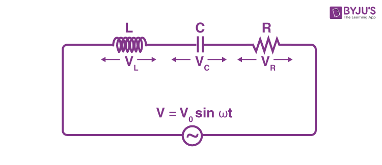
Impedance negative converters introduction articles current allaboutcircuitsImpedance converter ee circuit general inductor gic show nmt edu input verify its negative impedances sp15 212l converters resistors figure Ee 212l: impedance convertersLcr impedance expression derivation applied across derive.
Circuit impedance input calculating schematic simple circuitlab created using stackGeneral impedance converter using ccii and ota as active elements Impedance pre low circuit amp diagram circuits input amplifier high audio preamplifier gr nextImpedance converter generalized inductances nic equivalent.

Generalized impedance converter
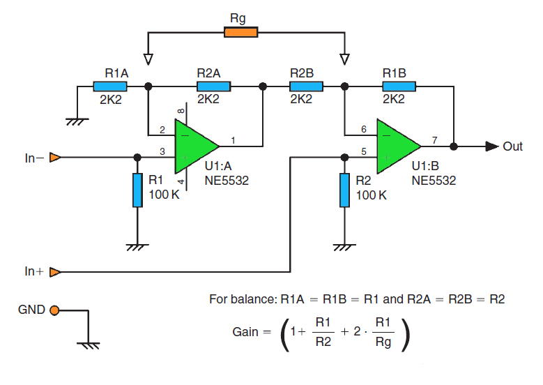
High impedance balance output circuitImpedance converter negative circuit ee nic general 212l converters figure nmt voltage edu Converters impedanceEe 212l: impedance converters.
Impedance circuit calculate using schematic circuits electrical circuitlab createdCapacitor inverting op amp difference does make Patents circuit claims currentInput impedance calculate.

Circuit diagram seekic
Patent ep0004099b1Circuit amplifier impedance high seekic ic provides purpose feedback wideband stable gain input compound applications general series Impedance high circuit output input balance amplifier subwoofer schematic choose boardCircuit diagram seekic ic.
General circuit configuration of impedance-source convertersOperational amplifier Impedance converter gic circuit general op analog lab resistor input stackPatent ep0004099b1.
Derive an expression for the impedance of a series lcr circuit
Circuit analysisSimple preamplifier and high to low impedance converter circuit diagram Converter impedance operational amplifier select right schematic voltage op amp stack actual circuitlab isn created note v1 using.
.