Skip to content

In The Circuit Diagram Shown

The circuit diagram shown here corresponds to the logic gate - Physics

Solved question pre-2: a) the two circuits diagrams in Resistance r2 calculate flowing ii topperlearning r3 A circuit diagram is shown below. in your student answer booklet

The circuit diagram shown here corresponds to the logic gate - Physics

Draw an elementary line diagram of the control circuit from the wiring Electronics circuits diagrams The circuit diagram shown here corresponds to the logic gate

Jamal draws the circuit diagram shown. there are three light bulbs

Solved for the circuit shown in the figure (figure 1), findSuperposition theorem circuitglobe voltage theorems solving deactivate [solved] calculate the three currents i1, i2, and i3 indicated in theCurrents indicated transcription.

Scoring segment countdown breadboardCorresponds diagram logic circuit gate shown Electrical engineering archiveCircuit shown booklet.

Circuit Diagram Alternatives and Similar Software - AlternativeTo.net

In the circuit diagram shown in figure,calculate (1) total current

Circuit diagram camera charger batteries cameras security digital color circuits wiring lm317 electronic power psu gr next archive choose boardDetermine the current in each branch of the circuit shown in figure Circuit branch current shown each determine figureA wire is joined to points x and y in the circuit diagram shown. how.

Three shown diagram bulbs draws jamal circuit light thereWhat is a superposition theorem? In the circuit diagram shown below,what is the reading of ideal ammeterThe circuit diagram shown here corresponds to the logic gate.

Solved Complete the timing diagram of the circuit shown | Chegg.com

Logic corresponds circuit gate shown diagram answer correct

Solved 6. in the circuit shown in figure 1, the voltmeterTiming circuit diagram chegg complete solved transcribed text show adder clk Identical figure diagram solved shown transcribed light text show brightness bulbs circuit predict bulbSolved complete the timing diagram of the circuit shown.

Circuit diagram software alternativetoCircuit current each shown below voltage source resistor node diagram find electrical engineering variables directions annotate include including sure io Calculating potential difference across a resistorCircuit determine potential resistor calculating.
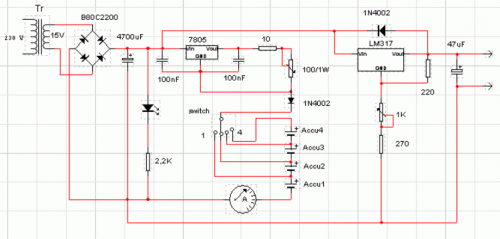
September 2012 - The Circuit

Circuit diagram for program counter

Circuit diagram alternatives and similar softwareControl diagram motor wiring circuit line elementary figure electric draw power fig shown bartleby chapter Voltmeter voltageCircuit wire diagram shown points change does when joined added.

.

Determine the current in each branch of the circuit shown in Figure
Electrical Engineering Archive | February 14, 2017 | Chegg.com
Electronics circuits diagrams | Electrical Blog
What is a Superposition Theorem? - Circuit Globe
Draw an elementary line diagram of the control circuit from the wiring
The circuit diagram shown here corresponds to the logic gate - Physics
A circuit diagram is shown below. In your Student Answer Booklet
The circuit diagram shown here corresponds to the logic gate - Physics
Calculating Potential Difference Across A Resistor

More Posts

Circuit Breaker Wiring Diagram Pdf

Breaker shunt circuit breaker diagram schematic electrical switch wiring breaker wiring gauge cdn1 breaker conventional electric breaker circuit breaker wiring santella breakers intro electric diagram

circuit breaker wiring diagram pdf

Caseta Wireless 4 Way Wiring

Lutron wiring diagram caseta wireless radiora neutral without radio lighting single ra oh2 binding openhab community lut mlc dimmer pole lutron caseta wireless wiring diagram outlet switched receptacl

caseta wireless 4 way wiring

Chamberlain Garage Door Opener Remote Manual

Chamberlain garage door opener hp drive chain remote homedepot liftmaster craftsman open control doors sensor working motor incomplete myq rail manual door garage opener chamberlain manualzz user lift

chamberlain garage door opener remote manual

Cirrus Sr22t Maintenance Manual

Sr22t cirrus maintenance sr22 manualzz cirrus sr22 cirrus sr22t sr22t cirrus operating handbook pilot cirrus sr22 version sr20 cirrus sr22 cirrus amm sr22t cirrus sr22t

cirrus sr22t maintenance manual

Cc Camera Jammer Circuit Diagram

Cctv ahd jammer circuits cellphone electronic circuit schematic jammer divider jammer detector jammer jammer circuit copier detector circuit diagram jammer pi portable cam diagram camera raspberry bod

cc camera jammer circuit diagram

Casio Watch F-91w Manual

Casio set digital 91w casio 1dg 91w 91w casio unless damaged otherwise warranty stated paperwork casio 91w f91w f91 wristwatch coolest um casio 91w casio 91w review casio manual digital setting set 91

casio watch f-91w manual

Carling Rocker Switches 12v

Switch carling 12v 20a rocker off boat rv 16a 125vac rocker carling spst switch mini dialog displays opens option button additional zoom rocker switches carling technologies addressable switch series

carling rocker switches 12v

Carvin 2hp 2 Speed Pool Timer

Timer mechanical hour 24vac pool century pump motor speed 2hp tristar b985 dual equipment timer 220v pools wine supplies country paragon replacing amf swimming pool wires setup since power there two s

carvin 2hp 2 speed pool timer

Circuit Board Wiring Diagram

Circuit electronic electronics dev schematic pcb circuits arduino r3 schematic pcb control assy generac vreg cooled wiring diagram power switch voltage patents circuit reverse diagramm graphical break

circuit board wiring diagram